Archive for the ‘crystal_structure_mining’ Category

Another very large anomeric effect – with a twist.

Thursday, July 22nd, 2021

In the earlier post on the topic of anomeric effects, I identified a number of outliers associated with large differences in the lengths of two carbon-oxygen bonds sharing a common carbon atom.

Here is another of these outliers (MUZZIS[1]) which shows equally unusual properties. This is an oxyanion (counterion is trimethylbenzylammonium) which is part of a very strong O-H-O hydrogen bond in which the O…O distance is 2.44Å and the O-H distances are each indicated as 1.23Å, suggesting the hydrogen is symmetrically disposed about the two oxygens. The anomerically lengthened C-O bonds (shown in red below) are 1.513/1.516Å, which is indeed long for a C-O bond.

A ωB97XD/Def2-SVPP/SCRF=chloroform calculation reveals a less symmetrical hydrogen bonding system, with calculated O-H distances of 1.046/1.434 (mean 1.24Å) and an O-O distance of 2.48Å. The anomerically lengthened C-O distances are 1.479/1.582Å. There are several reasons for these differences:

  1. The temperature at which the X-ray data were recorded was 173K and it remains possible that the data represent an averaged position for the atoms at this temperature rather than a truly symmetrical hydrogen bond.
  2. The basis set/DFT method for the calculation may itself favour unsymmetrical hydrogen bonds.

The two NBO energy perturbation terms for one lone pair on the oxygens interacting with the empty C-O σ* orbital are 31.6 and 57.5 kcal/mol. If the hydrogen bond is in reality entirely symmetric, then the NBO term would be expected to be approximately the average of these two values.

Click image to obtain 3D model

The earlier record anomeric holder achieved this by virtue of charge relocation involving an oxenium cation rather than the normal effect of charge separation. Here we have a similar effect, this time involving oxy-anionic charge relocation. Both are therefore special cases.

References

  1. R. Bengiat, M. Gil, A. Klein, B. Bogoslavsky, S. Cohen, and J. Almog, "Bis(benzyltrimethylammonium) bis[(4<i>SR</i>,12<i>SR</i>,18<i>RS</i>,26<i>RS</i>)-4,18,26-trihydroxy-12-oxido-13,17-dioxaheptacyclo[14.10.0.0<sup>3,14</sup>.0<sup>4,12</sup>.0<sup>6,11</sup>.0<sup>18,26</sup>.0<sup>19,24</sup>]hexacosa-1,3(14),6,8,10,15,19,21,23-nonaene-5,25-dione] sesquihydrate: dimeric structure formation<i>via</i>[O—H—O]<sup>−</sup><i>negative charge-assisted hydrogen bonds (–CAHB)</i>with benzyltrimethylammonium counter-ions", Acta Crystallographica Section E Crystallographic Communications, vol. 72, pp. 399-402, 2016. https://doi.org/10.1107/s2056989016002899

Two record breakers for the anomeric effect; one real, the other not.

Thursday, July 1st, 2021

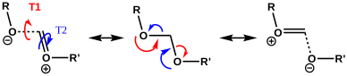
The classic anomeric effect operates across a carbon atom attached to oxygens. One (of the two) lone pairs on the oxygen can donate into the σ* orbital of the C-O of the other oxygen (e.g. the red arrows) tending to weaken that bond whilst strengthening the donor oxygen C-O bond. Vice versa means e.g. the blue arrows weakening the other C-O bond. This effect tends to increase charge separation and the question then arises: how large can this effect get? To try to find out, we are going to do some crystal structure mining in this post!

I need to list the parameters defining this crystal mining.

  1. Firstly, we note that the donating lone pair has to overlap in an anti-periplanar fashion with the C-O bond that is going to weaken. To get a handle on this overlap we are going to define the absolute value of the two torsion angles, T1 and T2 (minimum value 0° and maximum value 180°). Since a lone pair has no defined position in crystallographic coordinates, we will have to infer the angle of the lone pair from that of the torsion angles RO-CO and R’O-CO, which will then constitute a measure of how the oxygen lone pairs are oriented.
  2. If T1 or T2 have values of ~60° we might infer that one lone pair torsion may have a value of 60+120° = 180° and therefore that it is indeed antiperiplanar to a C-O bond.
  3. Next we define the two C-O distances. If BOTH the oxygen lone pairs are oriented at ~180° to the C-O bond, then both the red and the blue resonances can occur more or less equally and so each C-O bonds is both strengthened and weakened. The anomeric effect operates in both directions, meaning the two C-O bond lengths are more or less equal in length.
  4. If however only one of the lone pair torsions is 180° and not the other, a bond length inequality will be set up, which can be detected crystallographically.

Now for a search of the Cambridge crystal structure database. The definition is shown below, and included constraining the central carbon to 4-coordination (R = C or H), no errors and R < 0.05. 

Firstly the result for the two C-O distances. The point ringed in red is clearly an error, but the two ringed in green are real (IFJIO and IFEJUA) for which extreme inequality of the two C-O bond lengths appears. But before discussing this, I note that there is a double “hot spot” (red) for which the two C-O distances are more or less equal.

By constraining one of the R groups to R=H, a single hot spot is obtained showing unequal bond lengths (~1.395, 1.430Å) whilst the double hot spot only appears when both R are C. Something  interesting  going  on  there?

Next, a torsion plot is more directly revealing of an operating anomeric effect. The hot spot appears at values of each torsion of 60° which suggests that the most common conformation for these molecules is to have both oxygen atoms aligning with one lone pair antiperiplanar to the other C-O bond. This would not result in bond length inequality.

However, the remaining distribution shows both a vertical and a horizontal distribution in which only one of the oxygen atoms aligns a lone pair antiperiplanar to the C-O bond. According to the argument presented above, these should show bond length inequality. To check that the distribution above is not due to constraints of rings, a search in which both C-O bonds are specified as acyclic (i.e. not part of a ring) reveals the same effect.

Next, we combine both the distance and the torsion values as below. The mean of both torsion angles at 60° is again a hot-spot and this is associated with no difference in the two bond lengths. Conversely, the maximum difference in the bond lengths occurs at a mean torsion of ~ 90°, which can occur when the individual torsions are 60 and 120°, the former of which implies a lone pair is antiperiplanar to the  C-O bond. The rings again correspond to those identified above. 

Now to investigate those ringed molecules. The red one is SUCROS35[1] which was reported in 2012 as a high pressure polymorph of sucrose in which the hydrogen bonding pattern of regular sucrose has been substantially modified. Could application of pressure really induce an enormous anomeric effect?

SUCROS35

One way of applying a “reality check” is to calculate the geometry at a high level DFT level (ωB97XF/Def2-TZVPPD) which reveals that the three C-O bond lengths annotated above are predicted as 1.400, 1.416 and 1.392Å (FAIR Data DOI: 10.14469/hpc/8374). These are regular C-O lengths and exhibit nothing unusual. We might conclude that the crystal data for this specific set of coordinates is in error and should certainly be re-investigated. 

The two real examples of large bond length difference are both related[2] and the larger of which is the version with R=H,C rather than R=C,C. The example with  R=H is certainly augmented because of the hydrogen bond set up to the triflate group, which tends to forming an oxyanion, which is a stronger electron donor than e.g. methoxy.

IFEJIO

IFEJUA

The reason for these record breakers is that the anomeric effect in this case induces not so much charge separation as charge relocation. One way of quantifying the effect is to calculate the NBO E(2) interaction term between the donating oxygen lone pair and the accepting C-O σ* orbital. Click on the image below to view this interaction (blue = magenta; red = orange).

The values are 60.8 (IFEJIO, structure at DOI: 10.5517/cc111jxj), 46.5 (IFEJUA, structure at DOI: 10.5517/cc111jyk) and 20.8 (SUCROS35, structure at DOI: 10.5517/ccx16sx) kcal/mol. The latter in fact corresponds to a “normal” anomeric effect, which shows that our two record breakers are more than twice as large!

I conclude by noting that in the above distribution plots, there are five or so other “outliers” which need verifying and which may also prove interesting.  We have yet to find the largest anomeric effect exhibiting charge separation rather than relocation.

References

  1. E. Patyk, J. Skumiel, M. Podsiadło, and A. Katrusiak, "High‐Pressure (+)‐Sucrose Polymorph", Angewandte Chemie International Edition, vol. 51, pp. 2146-2150, 2012. https://doi.org/10.1002/anie.201107283
  2. G. Gunbas, W.L. Sheppard, J.C. Fettinger, M.M. Olmstead, and M. Mascal, "Extreme Oxatriquinanes: Structural Characterization of α-Oxyoxonium Species with Extraordinarily Long Carbon–Oxygen Bonds", Journal of the American Chemical Society, vol. 135, pp. 8173-8176, 2013. https://doi.org/10.1021/ja4032715

A reality-based suggestion for a molecule with a metal M⩸N quadruple bond.

Thursday, May 13th, 2021

I noted in an earlier post the hypothesized example of (CO)3Fe⩸C[1] as exhibiting a carbon to iron quadruple bond and which might have precedent in known five-coordinate metal complexes where one of the ligands is a “carbide” or C ligand. I had previously mooted that the Fe⩸C combination might be replaceable by an isoelectronic Mn⩸N pair which could contain a quadruple bond to the nitrogen. An isoelectronic alternative to FeC could also be FeN+. Here I explore the possibility of realistic candidates for such bonded nitrogen.

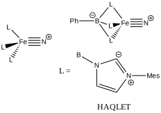
So I follow the strategy set in the previous post of conducting a crystal structure search of molecules containing the sub-structure L3-MN or L4-MN. Of the 85 hits for the former (FAIR DOI 10.14469/hpc/8196), I focus on those where N has only one bonded atom (to the metal M) and the ligand L is non-anionic connecting to the metal via e.g. carbon or phosphorus. This reduces to 11 hits, which in fact contain something similar to the Arduengo “carbene” ligand L shown below, this being known as a phosphine replacement. Here I look at one of these molecules, the internal ion-pair where the positive charge on the N is balanced by a four-coordinate negative boron, as in HAQLET.[2] (Data DOI: 10.5517/ccdc.csd.cc1p0mp0).

As with (CO)3Fe⩸C, L3Fe⩸N+ has a filled 18-electron metal valence shell. A ωB97XD/Def2-SVPD calculation on a simplified model (with aryl groups replaced by H) reveals the following NBO localised orbitals.

M-N, r = 1.475Å.
NBO 72, Occupied, Non-bonding d-orbital NBO 71, Occupied, Non-bonding d-orbital
NBO 67 π bond NBO 66 π bond
NBO 59 σ bond NBO 27 σ bond

There are two σ-bonds and two π-bonds between the Fe and the N. The molecule is presumably inhibited from reaction such as e.g. dimerising, because the iron-bonded nitrogen atom sits in a well created by the mesityl groups, thus sterically preventing any N…N approach close enough and at the appropriate angle to unite the two units. The free energy of dimerisation of the unhindered model used above is -49.7 kcal/mol.

I remind that the NBO method being used to ascertain the nature of the bonding here is a binary method, giving localised NBO orbitals with ~2e occupancies that contain an integer number of bonding orbitals between any pair of atoms. In this case, these can point to either a triple or a quadruple M…N bond for such systems and do not allow for a continuum approach where the weight of each localised bond might not be close to an integer. The purpose here is to flag this system for further analysis rather than as a definitive declaration of its quadruple-bonded nature.

References

  1. A.J. Kalita, S.S. Rohman, C. Kashyap, S.S. Ullah, and A.K. Guha, "Transition metal carbon quadruple bond: viability through single electron transmutation", Physical Chemistry Chemical Physics, vol. 22, pp. 24178-24180, 2020. https://doi.org/10.1039/d0cp03436c
  2. L. Bucinsky, M. Breza, W. Lee, A.K. Hickey, D.A. Dickie, I. Nieto, J.A. DeGayner, T.D. Harris, K. Meyer, J. Krzystek, A. Ozarowski, J. Nehrkorn, A. Schnegg, K. Holldack, R.H. Herber, J. Telser, and J.M. Smith, "Spectroscopic and Computational Studies of Spin States of Iron(IV) Nitrido and Imido Complexes", Inorganic Chemistry, vol. 56, pp. 4751-4768, 2017. https://doi.org/10.1021/acs.inorgchem.7b00512

Two new reality-based suggestions for molecules with a metal M⩸C quadruple bond.

Saturday, May 8th, 2021

Following from much discussion over the last decade about the nature of C2, a diatomic molecule which some have suggested sustains a quadruple bond between the two carbon atoms, new ideas are now appearing for molecules in which such a bond may also exist between carbon and a transition metal atom. A suggested, albeit hypothetical example was C⩸Fe(CO)3[1]. Iron has a [Ar].3d6.4s2 electronic configuration and if we ionise to balance a C4- ligand, the iron becomes formally FeVI or [Ar].3d4. By adding 14 electrons deriving from the seven “bonds” to the 3d4, including a quadruple count from carbon, the Fe formally completes its 18-electron valence shell, as also found in e.g. Ferrocene.

A search for crystal structures containing the very simple query structure shown below, where C is defined as having one atom only attached, TR is any transition metal and the structure is non-polymeric, was undertaken to see if any examples of this motif might already exist. 

Zero hits with 4-coordinate metal atoms, but 11 real examples were found (FAIR DOI 10.14469/hpc/8190), all of which exhibit a five-coordinate transition metal centre, where X is a mono-anionic ligand (CN, halogen, etc) and L is a neutral ligand (PR3 etc). The most common metal was M = Ru, the electronic configuration of which is [Kr].4d75s1, becoming [Kr].4d2 by ionising to balance a C4- ligand and the two X ligands. There are now 16 electrons from the eight “bonds” surrounding the atom, including again a quadruple one from the carbon and forming a filled 18-electron valence shell around the metal.

So could these 11 constitute known examples of quadruple bonds from a transition metal to carbon? I will investigate using M=Ru, L = PH3 and X = CN, which represents a simplified form of one of the 11 examples[2] using the following electronic model: ωB97XD/Def2-SVPD. The focus will be on five localised NBO orbitals (the procedure I used previously to count the number of bonds at carbon for C⩸Fe(CO)3).

For M=Ru, the NBOs emerge as follows (click on any orbital thumbnail to convert to a 3D rotatable model).

M=Ru, r = 1.624Å.
NBO 42, Occupied, Non-bonding d-orbital NBO 41 π bond
NBO 36 π bond NBO 35 σ bond
NBO 34 non-bonding carbon lone pair Overlap of orbitals 42 and 34

This reveals only a triple Ru≡C bond plus a non-bonding lone pair on carbon. It turns out that bonding σ-orbital 34 is “surrounded” by the non-bonding Ru d-orbital 42. The electron-electron repulsions between the pair causes the electrons in orbital 34 to locate onto the carbon to form a non-bonding lone pair, as thus:

So might it be possible to persuade this carbon lone pair to instead donate into the M-C bond to form that fully-fledged quadruple bond?

One simple strategy is to remove the two electrons in orbital 42, preventing the Pauli repulsions from occuring and this can be done by using Mo instead of Ru.

M=Mo, r = 1.673Å
NBO 42 unoccupied Non-bonding d-orbital NBO 41 σ bond
NBO 40 π bond NBO 39 π bond
NBO 22 σ bond

By removing the repulsions to the non-bonding d-orbital, we have now transformed the erstwhile carbon lone pair into a fully fledged bond as in orbital 22, thus forming the quadruple motif. There are two electrons less, so this time the Mo valence shell is a 16-electron system.

So, SUGGESTION 1:

The second possibility is to increase the size of the non-bonding d-orbital 42 by changing from Ru to Os. Here again, orbital 22 is less repelled by the electrons in orbital 42 due to the larger size of the latter and so can again become C-Os bonding rather than non-bonding carbon lone pair.

M=Os, r = 1.679Å
NBO 42 Occupied Non-bonding d-orbital NBO 41 π bond
NBO 40 σ bond NBO 35 π bond
NBO 22 σ bond

So, SUGGESTION 2

This approach also reveals the binary decision in the NBO analysis, either an orbital is classified as “LP” and hence is not considered a bond, or it is classified as “BD” and is a bond. Reality is certainly more nuanced, with weights needing to be assigned to each valence bond representation (rather than just 1.0 or 0.0). Probably also these weights will depend on a number of factors, such as basis set quality and the method applied (e.g. the DFT procedure used). So the binary terms “triple” or “quadruple” do not carry the full measure of the bonding behaviour, which may be a continuum between these two extremes. But the two molecules shown above do represent molecules that could be realistically synthesized, since they are but small variations of already known molecules. Once made, they could then be subjected to appropriate experimental analysis to test the bonding hypotheses made here.


This post has DOI: https://doi.org/gbq3


References

  1. A.J. Kalita, S.S. Rohman, C. Kashyap, S.S. Ullah, and A.K. Guha, "Transition metal carbon quadruple bond: viability through single electron transmutation", Physical Chemistry Chemical Physics, vol. 22, pp. 24178-24180, 2020. https://doi.org/10.1039/d0cp03436c
  2. T.J. Morsing, A. Reinholdt, S.P.A. Sauer, and J. Bendix, "Ligand Sphere Conversions in Terminal Carbide Complexes", Organometallics, vol. 35, pp. 100-105, 2015. https://doi.org/10.1021/acs.organomet.5b00803

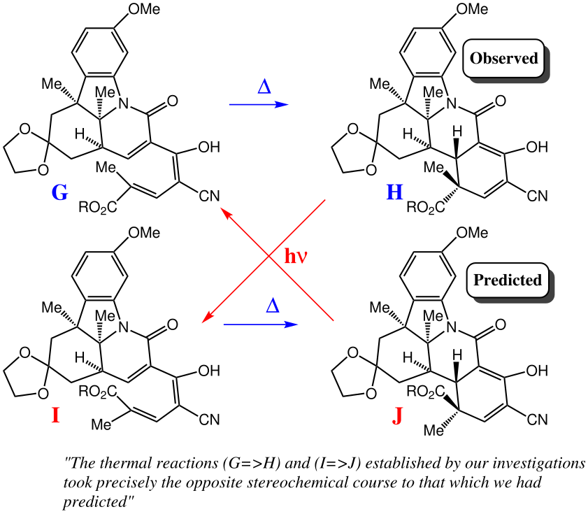
The thermal reactions … took precisely the opposite stereochemical course to that which we had predicted

Wednesday, January 20th, 2021

The quote of the post title comes from R. B. Woodward explaining the genesis of the discovery of what are now known as the Woodward-Hoffmann rules for pericyclic reactions.[1] I first wrote about this in 2012, noting that “for (that) blog, I do not want to investigate the transition states”. Here I take a closer look at this aspect.

Vitamin B12 synthesis

I will start by explaining my then reluctance to discuss transition states. Woodward in describing this discovery (in Chem. Soc. Special Publications (Aromaticity), 1967, 21, 217; a historic article which unfortunately remains off-line) notes the “steric preference for attack below the plane for C-5 and a gentle spiral for the cyclization to achieve the required stereochemistry at C-6″. In reference to the diagram above, he is talking about the reaction G to J which he thought was favoured over G to H on steric grounds. We must now try to judge what criteria might have been used to establish these steric grounds. He might have been referring to the relative thermodynamic stabilities of H vs J, which is the aspect I addressed in my earlier blog. But it has now been pointed out to me that Woodward is more likely to have been thinking about the transition state for the reaction, in referring to a “gentle spiral” for the reaction path as inferred by model building. So why my reluctance in 2012 to look at this aspect? As Woodward himself quickly came to realise, the transition state for G to H is electronically “allowed” but the transition state for G to J is electronically “forbidden”. Let me qualify that. The latter is only forbidden on the ground state electronic surface, but it is allowed on an open shell excited state (photochemical) surface. It is very difficult (if not impossible) to directly compare the energies of these two electronic states for any steric differences that might be hidden or embedded within them. So how did Woodward initially infer a “steric preference” between these two reactions?

Model building reached its peak as an essential tool for understanding chemistry in the 1950s, with the likes of Pauling and Watson + Crick making Nobel-prize winning discoveries using this technique. By the 1960s, one could buy commercial model building kits, such as Dreiding stereomodels (1958) which focused on the bonds themselves and CPK or spacefilling models (~1952[2]) based on the size of the atom (a technique pioneered by Loschmidt as long ago as 1860). I would point out that such models are constructed for molecules in their presumed ground electronic state! So Woodward must have been constructing models for G to H and G to J with the implicit assumption that they were in the ground electronic state. Clearly he noticed something which led him to conclude that these models predicted G to J over G to H. I do not know if his models have survived to posterity and are now in a museum somewhere; the chances are we will never know exactly what it was that alerted him that the formation of G to H was so unexpected that it triggered a Nobel-prize winning theory!

Having declined to build TS models in my original musings on this topic, I now decided to bite the bullet and try to now locate at least approximate models for both possible stereochemical outcomes. The disrotatory transition state for G to H is relatively trivial. Here I used the PM7 method, which I noted previously nicely absorbs dispersion corrections which may be important! It also allows a full IRC for the reaction path to be constructed in just a few hours (a DFT approach would take quite a lot longer). The FAIR data for my models can be found at DOI: 10.14469/hpc/7806

I then realised that the electronically “forbidden” transformation G to J (something that makes locating a transition state on the ground state surface unlikely) was in fact allowed for an open shell triplet state (a excited state). In this state, transition state location actually proceeds without issue to find a nice conrotatory transition state.

The two key transition state models are each shown below in two representations. The clashes noted are approaches of two atoms closer than the sum of the van der Waals radii. First, I note that transition state G to H clashes a hydrogen with the adjacent methyl group (H…H contact 1.937Å using the PM7 semi-empirical method, 1.942Å using the ωB97XD/6-311G(d,p) density functional method).

G to H, ball and stick representation. Click to view 3D

G to H, spacefilling representation

G to J also exhibits a clash, albeit a lesser one, between the hydrogens of two methyl groups (2.01Å for PM7, 2.03Å for ωB97XD/6-311G(d,p)). So one could argue that G to J is indeed favoured on steric grounds over G to H, but only by about 0.07Å in the close approach of pairs of non-bonded hydrogen atoms. I also note that Woodward’s gentle spiral or spiral of low pitch is in fact a left-handed one!

G to J, ball and stick representation. Click to view 3D

G to J, spacefilling representation.

To get another perspective on what this means in reality, I conducted a search of the CSD (Cambridge structure database) for the sub-structure shown below:

The results show H…H contacts down to about 2.03Å, which suggests that the steric clash for G to H probably is slightly repulsive, whilst that for G to J could be on the verge of being attractive.

We might conclude that there is probably only a small steric difference between the two quantitative reaction models G to H and G to J as evaluated here, probably favouring the latter and assuming that the sterics are expressed entirely by van der Waals distances and have not been absorbed into bond angles etc. Of course much of what I have done and explained here was not common in the 1960s. The details of how Woodward’s models were actually constructed and how quantitative they were may never be discovered. It matters not of course, since the surprise of finding the actual product was H and not J went on to catalyse one of the great theories of organic chemistry!


My thanks to Jeff Seeman and Dean Tantillo for contacting me about this, inspiring the above revisitation and much interesting discussion; J. Seeman and D. Tantillo, “On the Structural Assignments Underlying R. B. Woodward’s Most Personal Data Point That Led to the Woodward-Hoffmann Rules. Related Research by E. J. Corey and Alfred G. Hortmann.”, Chem. Euro. J., 2021, in press. As noted elsewhere on this blog, H…H contacts as short as 1.5Å have been measured experimentally. To turn the 3D view of the molecule into a spacefill model, right-click in the model window and invoke Scheme/CPK Spacefill as shown below:

References

  1. R.B. Woodward, and R. Hoffmann, "Stereochemistry of Electrocyclic Reactions", Journal of the American Chemical Society, vol. 87, pp. 395-397, 1965. https://doi.org/10.1021/ja01080a054
  2. R.B. Corey, and L. Pauling, "Molecular Models of Amino Acids, Peptides, and Proteins", Review of Scientific Instruments, vol. 24, pp. 621-627, 1953. https://doi.org/10.1063/1.1770803

Fascinating stereoelectronic control in Metaldehyde and Chloral.

Tuesday, June 9th, 2020

Metaldehyde is an insecticide used to control slugs. When we unsuccessfully tried to get some recently, I discovered it is now deprecated in the UK. So my immediate reaction was to look up its structure to see if that cast any light (below, R=CH3, shown as one stereoisomer).

A X-ray crystal structure exists (DOI: 10.5517/ccdc.csd.cc20n2pg) and reveals it to be the tetramer of acetaldehyde, or (CH3CHO)4. One further structure came to light, another tetramer of trichloromethylacetaldehyde, known as chloral.[1] This latter compound forms a hydrate, hence chloral hydrate. These two compounds, differing only in the methyl group, show very different conformations of the eight-membered rings. As to why this is, makes for a fascinating story.

Click to obtain 3D model

Firstly, the approach I used. I optimised the structure from the crystal data using ωB97XD/Def2-TZVPP, using C4v symmetry in which all four of the methine hydrogens point in the same direction. The resulting four H…H contacts of 2.13Å are on the short side, and are certainly contributing to the stability by dispersion (London) attractions. The C-O distances are 1.399Å. I then did an ELF (Electron localisation function) analysis to identify what are called the monosynaptic basins. Better known as lone pairs! These (along with the disynaptic basins along the C-O bonds) are shown in purple above. I have displayed the torsion or dihedral angles between each of the lone pairs on oxygen and the adjacent C-O bond (150.1 and 42.0°). This now reveals the so-called anomeric effects in the molecule. Basically one of the lone pairs on oxygen has eight sets of 150.1 angles and the other lone pair eight sets of 42.0°. Only the former lone pairs are close to being anti-periplanar to the adjacent C-O bond. In this geometry, this lone pair can donate into the C-Oσ* orbital of the bond. One can quantify the strength of this interaction using NBO (natural bond orbital) analysis, which gives a so-called E(2) perturbation interaction energy of 19.7 kcal/mol, in total eight of them. The other lone pair on each oxygen shows no discernible interaction.

On to Chloral (X = CCl3). This shows an entirely different geometry with Ci symmetry. This has two distinctly different pairs of oxygen atoms, with a pair of 2.36Å H…H contacts and two pairs of C-O distances 1.406 and 1.378Å; 1.406 and 1.380Å. This asymmetry immediately implies chloral will be more reactive towards e.g. hydrolysis, since one of the C-O bonds is already slightly lengthened. There are 16 distinct dihedral values between an oxygen lone pair and either an adjacent C-O or a C-CCl3 bond. The largest has a torsion angle at C-O of 161.2° with an NBO E(2) energy of 20.6 kcal/mol for a C-O interaction; the other torsions are 149.9, 141.1, 127.5, 112.6, 112.0, 111.1, 74.6, 68.2, 54.1, 42.6, 38.7, 32.6, 20.7, 5.7 and 4.1. There is a new anomeric effect to the adjacent C-CCl3 bond of 12.1 kcal/mol, lower for this latter interaction because the angle (113°) is far from the ideal 180°. In this model, all eight oxygen lone pairs play a role in stabilising the molecule, whereas in metaldehyde only four lone pairs do this.

Click to obtain 3D model

One can now transpose the symmetry of each molecule onto the other compound. Metaldehyde in Ci symmetry is +5.5 kcal/mol higher in free energy and chloral in C4v symmetry is +3.9 kcal/mol. The origins of these difference are probably dissipated across the multiple anomeric effects and H…H dispersion attractions.

This technique of locating the centroids of lone pairs using ELF and then correlating the dihedral angle between the lone pair and any adjacent C-X bond (X = electronegative, which makes the C-X bond a good electron acceptor) is very useful in explaining instances of the anomeric effect and comparing them across isomers.

References

  1. D. Hay, and M. Mackay, "The crystal and molecular structure of metachloral, 2(e),4(e),6(e),8(e)-Tetrakis-(trichloromethy1)-1,3,5,7-tetraoxocan", Australian Journal of Chemistry, vol. 33, pp. 2249-2253, 1980. https://doi.org/10.1071/ch9802249

The first ever curly arrows. Revisited with some crystal structure mining.

Wednesday, May 27th, 2020

With the current global lockdown, and students along with everyone else staying at home, I have noticed some old posts of mine are getting more attention than normal. One of these is an analysis I did in 2012 of Robinson’s original curly arrow illustration. That and the fact that I am about to give a lecture on what I call my autobiographical journey discovering them, to our own students here (remotely of course), has prompted me to revisit my original discussion.

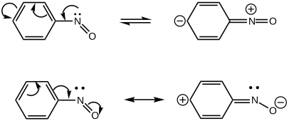
Of the two modern representations of nitrosobenzene, the first corresponds to Robinson’s arrows, being an attempt to show, by resonance, that the molecule is o/p directing towards an electrophile. Hence the accumulation of negative charge in the p-position (and other resonance structures can be drawn with it in the o-positions) encouraging electrophilic attack there. The second is the modern version, with the electron flow going in the other direction and hence discouraging electrophilic attack at the o/p positions. All this hinges on the observation that the nitrogen lone pair, involved in the first representation, lies in the plane of the molecule and hence is orthogonal (at 90°) to the π-electrons in the benzene ring and cannot overlap with them. In the modern view, this lone pair plays no part in the resonance. 

This can be tested by searching for experimental crystal structures of nitrosobenzenes. I did mention this in the original post, but showed no results. So here is the analysis, in which the plots below analyse the torsion about the phenylNO bond. You can see all the examples are either red or blue, which indicates torsions of ~180 or 0°. You can perceive a very nice correlation between the length of the C-N and the N-O bonds. As the latter gets shorter, the former gets longer. This only matches the second resonance shown above and not the Robinson version! Across all known crystal structures of nitrosobenzenes, the balance between these two resonance forms changes, no doubt as a result of substituents on the benzene ring. 

A different plot which now includes the angle at the nitrogen shows very little variation in that angle (113-118°), and certainly not the much larger variation implied by Robinson’s representation. As the N-O bond gets longer, so the angle at the nitrogen opens up a bit, the lone pair on the nitrogen being repulsed by the now three lone pairs on the oxygen anion.

I have noted previously that such crystal structure mining can be used to capture many basic concepts in chemistry.[1] This is a particularly clear one, discriminating between two possible forms of curly arrow. Conversely, it shows how curly arrows can be used to simply rationalise structural variations across a series of compounds.


There is one outlier (it does not appear in the plots above, since these are restricted to structures with an R-factor <5%), that shows a linear Ph-N=O system (DOI: 10.5517/cc108dl8) and which may be a Robinson-like valence bond isomer of nitrosobenzene. It will be investigated further!

References

  1. H.S. Rzepa, "Discovering More Chemical Concepts from 3D Chemical Information Searches of Crystal Structure Databases", Journal of Chemical Education, vol. 93, pp. 550-554, 2015. https://doi.org/10.1021/acs.jchemed.5b00346

The strongest bond in the universe: A crystallographic reality check?

Monday, May 25th, 2020

My previous two posts on the topic of strongest bonds have involved mono and diprotonating N2 and using quantum mechanics to predict the effect this has on the N-N bond via its length and vibrational stetching mode. Such species are very unlikely to be easily observed for verification. But how about a metal M+ instead of H+? It turns out that structures containing the fragment Ru-N≡N-Ru are a small but well studied class of organometallic. Here is a search of the CSD crystal database for this motif.

The three examples showing the shortest N-N distances are shown below.[1],[2][3]

The NN distances for these three examples are in the region of 1.1Å. There are 39 structures in total, for a variety of other transition metals, with a length <1.15Å. The angles subtended at N are close to linear;


For comparison, N2 itself entrained into a crystal structure has the value of ~1.096Å as measured at 80K (R-factor 0.84%)[4]) which is pretty similar to the value computed in the previous post (1.103Å).  

So the question to ask is whether any of these organometallic examples have an NN bond at least as strong as that in dinitrogen itself? Only a reliable value for the force constant will give us a clear picture, which however would be non-trivial for such species. But it does suggest that asking whether there could be a real candidate for the strongest bond in the universe other than N2 itself may not be entirely futile.


References

  1. Y. Sun, H. Chan, and Z. Xie, "Reaction Scope and Mechanism of Sterically Induced Ruthenium-Mediated Intramolecular Coupling of<i>o</i>-Carboranyl with Cyclopentadienyl. Synthesis and Structure of Ruthenium Complexes Incorporating Doubly Linked Cyclopentadienyl−Carboranyl Ligands", Organometallics, vol. 25, pp. 4188-4195, 2006. https://doi.org/10.1021/om0604122
  2. Y. Tanabe, S. Kuriyama, K. Arashiba, K. Nakajima, and Y. Nishibayashi, "Synthesis and Reactivity of Ruthenium Complexes Bearing Arsenic-Containing Arsenic-Nitrogen-Arsenic-Type Pincer Ligand", Organometallics, vol. 33, pp. 5295-5300, 2014. https://doi.org/10.1021/om5006116
  3. K. Abdur-Rashid, D.G. Gusev, A.J. Lough, and R.H. Morris, "Synthesis and Characterization of RuH<sub>2</sub>(H<sub>2</sub>)<sub>2</sub>(P<sup>i</sup>Pr<sub>3</sub>)<sub>2</sub> and Related Chemistry. Evidence for a Bis(dihydrogen) Structure", Organometallics, vol. 19, pp. 1652-1660, 2000. https://doi.org/10.1021/om990669i
  4. C. Dou, W. Kosaka, and H. Miyasaka, "Gate-open-type Sorption in a Zigzag Paddlewheel Ru Dimer Chain Compound with a Phenylenediamine Linker Instructed by a Preliminary Structural Change of Desolvation", Chemistry Letters, vol. 46, pp. 1288-1291, 2017. https://doi.org/10.1246/cl.170509

A molecular sponge for hydrogen storage- the future for road transport?

Sunday, April 19th, 2020

In the news this week is a report of a molecule whose crystal lattice is capable of both storing and releasing large amounts of hydrogen gas at modest pressures and temperatures. Thus “NU-1501-Al” can absorb 14 weight% of hydrogen. To power a low-polluting car with a 500 km range, about 4-5 kg of hydrogen gas would be need to be stored and released safely. The molecule is of interest since it opens a systematic strategy of synthetically driven optimisation towards a viable ultra-porous storage material,[1] much like a lead drug compound can be optimised.

I thought it would be informative to show a 3D interactive model of the crystal lattice here and so I went in search of coordinates. These are indeed available online. This is an example of scientific data Interoperability and Reuse, part of the FAIR data acronym. Before showing the model, I thought it worth briefly describing the procedure for starting with deposited data and converting (interoperating) it to the model here.

  1. The molecule is a so-called MOF, or Metal-Organic-Framework. The core organic framework in this case is composed of linked tryptycene derivatives. Shown below is the 3D structure of this linker, oriented here to show the three-fold symmetry (actually D3) of the molecule, rather than any attempt to reveal all the atoms without any hidden ones. To see the latter, you are encouraged to click on the diagram and view the molecule as a rotatable model instead. The coordinates below are optimised using molecular mechanics to reveal the role of the linker units.

Click for a rotatable 3D model.

  1. The data comes in the form of a CIF (crystallographic information) file and needs to be loaded into software that can manipulate such a format. In this case a program called Mercury (from CCDC) is available. Doing so reveals two minor oddities, circled in red below. The phenomenon arises from disorder, or two or more structures each with what is called partial occupancy. In this case, the disorder is largely limited to a p-substituted phenyl spacer linkage, which can adopt one of two rotational positions in the structure. The projection below is now selected to reveal the disorder rather than the symmetry.
  2. I want to “inter-operate” these coordinates into something that can be modelled and for this, the structure has to be edited to reduce it to a single unambiguous model. My very simple expedient here was simply to remove extraneous disordered atoms entirely; since they are acting as a spacing unit, this is unlikely to change the overall picture. Again, the projection below is selected to show the symmetry present and in particular the hexagonal-like channels that appear in the crystal lattice. To achieve this lattice, the unit cell has to be grown in all three directions using the calculate packing option in the Mercury program.

Click for 3D rotatable model

Clearly, the hexagonal cavities formed can accommodate a large number of hydrogen molecules. As to why, it is no doubt complex, but I cannot help but notice that the surface of the cavity is lined with multiple C-H units from the aryl spacer units pointing inwards. Given that hydrogen is a very good inducer of dispersion attractions, it would be interesting indeed to see whether the very large number of H…H2 dispersion attractions possible inside the cavity of this species might at least in part be responsible for the ability of this framework to accommodate hydrogen (or methane) gas.[2] It would be good to have an estimate of the dispersion energy term for NU-1501-Al and related species and the contribution of this term to the overall thermodynamics of the system. By the same token, replacing the four aryl C-H units with C-F units (a weaker dispersion attractor, think non-stick teflon) should reduce the ability to absorb hydrogen if dispersion is indeed important.


On the other hand, if the orientation of the aryl C-H groups is important in terms of dispersion attractons, perhaps these groups are actually critical to the effect.

References

  1. Z. Chen, P. Li, R. Anderson, X. Wang, X. Zhang, L. Robison, L.R. Redfern, S. Moribe, T. Islamoglu, D.A. Gómez-Gualdrón, T. Yildirim, J.F. Stoddart, and O.K. Farha, "Balancing volumetric and gravimetric uptake in highly porous materials for clean energy", Science, vol. 368, pp. 297-303, 2020. https://doi.org/10.1126/science.aaz8881
  2. S. Rösel, C. Balestrieri, and P.R. Schreiner, "Sizing the role of London dispersion in the dissociation of all-meta tert-butyl hexaphenylethane", Chemical Science, vol. 8, pp. 405-410, 2017. https://doi.org/10.1039/c6sc02727j

Choreographing a chemical ballet: a story of the mechanism of 1,4-Michael addition.

Monday, April 13th, 2020

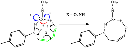
A reaction can be thought of as molecular dancers performing moves. A choreographer is needed to organise the performance into the ballet that is a reaction mechanism. Here I explore another facet of the Michael addition of a nucleophile to a conjugated carbonyl compound. The performers this time are p-toluene thiol playing the role of nucleophile, adding to but-2-enal (green) acting as the electrophile and with either water or ammonia serving the role of a catalytic base to help things along.

The scheme above is deliberately set out as an eight-membered ring so that if the three dancers wish to do so, they can all act in concert. Oh, there is also a bit-actor (water) forming a hydrogen bond to X, the role of which will become clearer as the ballet proceeds. The curly arrows indicate what the electrons in the bonds or the lone pairs are expected to do. The three black arrows can be accompanied by either two blue arrows to give five in all, or just four if the two blue arrows are replaced by a single red one.

The choreographer in our performance is actually going to be a density functional quantum mechanical calculation (ωB97XD/Def2-TZVPP/SCRF=water, data at DOI: 10.14469/hpc/7027 since you ask), which has the single minded intention of ensuring that the cast is at the lowest possible energy at each stage of the ballet. The performance is shown below with X=O in the cast (water). Water is a poor base; its ability to grab a proton is weak. 

We can also show the entire dance using an Intrinsic Reaction Coordinate or IRC, this being the lowest energy pathway that the cast can achieve along this particular route to the end. Watch the animation above to see the performance! The catalyst (X=O remember) firstly gets into the best position to grab a proton from the S-H group, using its lone pair located on the oxygen (the base). It is helped by the bit-playing second water molecule, which forms an assisting support to the (lets call her) ballerina via a strong hydrogen bond. Having grabbed the proton from the ballerino, the catalyst transforms (temporarily) into a hydronium cation, paired now with a thiolate anion as an ion-pair. Temporarily, because this sort of arrangement is called a “hidden intermediate” in that this ion-pair is hidden, never actually forming. The water needs considerable help to become protonated (remember, it is a weak base), with the assisting water bit-player helping to stabilize the hydronium cation by a strong hydrogen bond it has formed.

The transition state for the reaction. Click to view 3D model. The vibration is that of the “transition state normal mode” as the molecule goes over the top of the barrier.

We now introduce the (relative) energy of the entire collection of molecules and have reached the stage of IRC=-1 on the X-axis. One final push is now needed, in which two things happen. Firstly, a S-C bond is formed (IRC = 0.0, the transition state) but as soon as it starts forming so does the rather unhappy hydronium cation relieve itself of the unwelcome proton it just acquired, by off-loading it onto the oxygen of the acrolein. You can see the structure of this transition state above (click on the image to turn it into a rotatable 3D model)
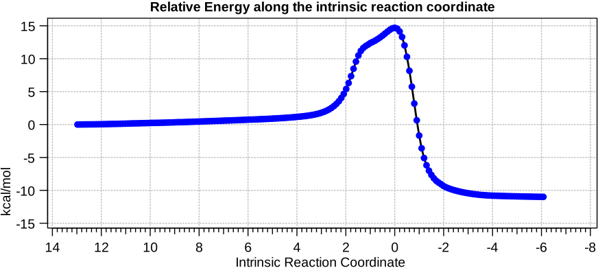
The catalyst is back to where it started (along with its bit-playing partner) and we now have a completed reaction and it all happened as a single act ballet (we call this a concerted performance). The products are lower in energy than the starting point, which is always good! Molecules tend to be lazy and do not much like becoming higher in energy (ATP, or adenosine triphosphate is a famously unlazy molecule which is very good at acquiring lots of energy and redistributing it about our bodies to feed our muscles).

We can look at another property which tells us a bit more about the curly arrows, which represent rearrangement of electrons within the molecule. If they get separated, their charges also become separated and this is reflected in the dipole moment along the reaction coordinate. In the early stages, blue arrow 1 starts to form a hydrogen bond from the lone pair of the water to the hydrogen on the S. As it does this, the dipole moment decreases. At the point that the proton finally decided to hop from the sulfur to the approaching water oxygen, the charge separation shoots up, reaching its maximum at IRC = -1 (IRC = 0 by the way represents the energy high point for the process, called the transition state).
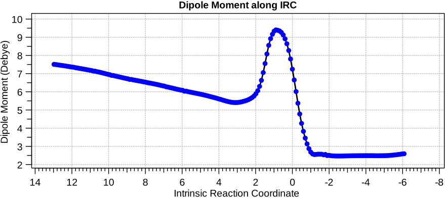
I want now to address the vital point of why I drew two different arrangements of curly arrows, one with two blue arrows (1 and 5) and the other with just one red arrow (6). If we had instead used just the latter, then we would have been obliged to transfer both protons at exactly the same time. So blue arrow 1 is a better representation of what is actually going on. Only now do the black arrows 24 get into the performance, forming the S-C bond (2), reducing the first double bond in the acrolein to single, whilst reforming it adjacently (3) and transforming the second C=O double bond into C-O and O-H bonds (4). This encourages the second blue arrow (5) to, concurrently with the black arrows, transfer a proton and reform the lone pair onto the original oxygen of the water catalyst.

Let us now change the cast, replacing the original water catalyst with an ammonia (X=NH). Because N has a smaller nuclear charge than oxygen, it is happier at sharing its lone pair with a proton; it is said to be more basic. This means that an ammonium cation is a more willing performer than the hydronium cation. The ballet now occurs in two acts rather than one. The first act involves that now basic nitrogen removing the proton from the SH (arrow 1+2), but with arrow 2 ending up residing entirely on the S (as a sulfur lone pair) rather than immediately going on to form a S-C bond.

Act 1: Proton transfer from N to S.

There is then an intermission when the newly formed ion-pair takes a break, followed by the second act starting with a slightly different arrow 2 (it starts not at the S-H bond, but put on a new costume during the break to start as a new lone pair formed on the S) creating the new S-C bond. There is another difference compared to the water catalyst; the ammonium cation is now slightly reluctant to relinquish that proton and this only happens right at the end.

Act 2: Carbon-sulfur bond formation/Proton transfer. Click to view 3D model.

The energy high point is again S-C bond formation (IRC = 0.0), and the barrier the molecules needed to overcome to reach the energy high point is much lower than before. The nitrogen hangs on to its newly acquired proton until IRC = -2 and the reaction does look complete by IRC = -10. But in a final flourish (let’s call it an encore) something happens between IRC -10 to -15. Miffed at having to part with a hydrogen it had become fond of, the nitrogen lone pair instead now makes friends with a C-H bond (as part of a hydrogen bond; it is not basic enough to entirely remove a hydrogen from a carbon). 

The language has been slightly anthropomorphic, but we have covered a lot of chemistry with this reaction and learnt a lot about the sequence in which bonds form and how curly arrows can be used to relate to this process.


The encore: We can check to see if this last part comes purely from the fevered imagination of the density functional calculation or whether there is a basis in reality for this new friendship. The plot below comes from a search of all known crystal structures for organic molecules (which recently passed one million). Of these, 21 exhibit a CH…N distance < 2.45Å and the “hotspot” (in red) indicates that the strongest of these is ~2.15Å and that the C-H…N angle is approximately linear. So the effect is real!


See also this post for the non-catalysed version of this reaction.


This post has DOI: http://doi.org/dr96