Posts Tagged ‘Reaction Mechanism’

Curly arrow pushing: another reality check.

Sunday, August 5th, 2012

Two years ago, I discussed how curly arrow pushing is taught, presenting four different ways of showing the arrows. One of the comments posted to that blog suggested that all of the schemes shown below were deficient in one aspect.

Curly arrow pushing

The issues were the stereo and regiochemistry. In particular, the diagram above carries no explicit information about the symmetry of the electrons from which the first arrow originates; it is considered only implicit that we are referring to the π-electrons of the alkene, and that this in turn imparts stereochemical information which is absent from the diagram itself. This deficiency can indeed be traced back to the first ever representation of curly arrows, where the distinction between π- and σ-electrons was not made, and which in that example can cause much confusion about the properties of the molecule being considered. It is in some respects surprising that a notation first proposed in 1924, in effect before quantum mechanics as applied to chemistry had properly matured, is still largely intact and unchanged since that day.

Are curly arrows ripe for reform? In order to try to move this debate forward, I decided to investigate precisely the reaction shown above using quantum mechanics (ωb97xd/6-311g(d,p)/scrf(cpcm=water)  The results will be presented as an intrinsic reaction coordinate of the precise reaction shown above. Before revealing it however, I should note that the scheme above in fact attempts to represent only part of a reaction; the formation of a carbocation by reacting propene with HBr. It does not reveal the end-game so to speak, in which the carbocation then reacts with the bromide anion to form 2-bromopropane. What is implied by the scheme above is that the propyl cation and bromide anion together constitute a discrete intermediate on the way to form this product, and that the overall reaction therefore comprises two discrete transition states and one intermediate; a stepwise reaction.

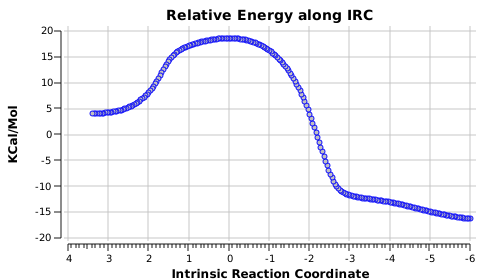
  1. The (optimised) geometry of the starting point (IRC = 3.5) is a hydrogen bonded complex between the alkene and the H-Br, interacting via the π-cloud of the former. This structure is offset from the mid-point of the double bond towards the less substituted end. We are here seeing Markovnikov’s rule in action.
  2. As a result, the proton transfer (IRC = 0.0) when it starts to happen, heads off for the terminal carbon rather than the middle one.
  3. After this point, note carefully that no intermediate carbocation/bromide anion pair is actually formed. Instead at about IRC -1.0, the bromide atom starts to move towards the central carbon to form a C-Br bond (IRC -2). The immediate outcome of this is that the newly formed C-Br and C-H bonds are conformationally eclipsed.
  4. At IRC -4, the final stage in the reaction starts to take place, a subtle rotation about the BrC-CH bond to remove its eclipsing nature.

If you compare this more quantitative scenario with that depicted in the original scheme at the top, you will notice that it does not capture the timing of any of the events described above and even  appears to be quantitatively wrong in showing a carbocationic intermediate. This last aspect perhaps is because a curly arrow diagram does not attempt to describe the environment in which a reaction might find itself, which in this case may be an explicit hydrogen bonding solvent or Lewis acid catalyst. Thus the bromide anion may be stabilised by other species present in solution, perhaps to the extent of even forming an ion pair.

The point to take home from this however is that perhaps the next evolution of (schematic) curly arrows might be towards more quantitative reaction coordinate diagrams, expressed (as here) as an animated IRC. Indeed, I am (slowly) assembling a library of these for some of the more common reactions to be found in organic chemistry. And we should not forget that even these are defined by the model we construct, which may not include all of the components and conditions actually present when the reactions occur in reality.
Cyclopentadiene: a hydrocarbon at the crossroads of …

Sunday, July 29th, 2012

organic chemistry. It does not look like much, but this small little molecule brought us ferrocene, fluxional NMR, aromatic anions and valley-ridge inflexion points. You might not have heard of this last one, but in fact I mentioned the phenomenon in my post on nitrosobenzene. As for being at a crossroads, more like a Y-junction. Let me explain why.
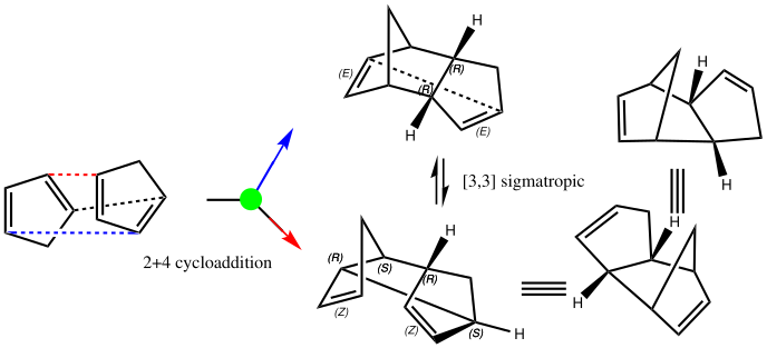
Cyclopentadiene is made by thermal cracking of its dimer, and on standing it slowly reverts to this species. At its simplest, this dimerisation can be described as a π2s + π4s pericyclic cycloaddition, one of the monomers being the π2s and the other the π4s. Two new bonds are formed; one of these is shown in black, but the other can be either the one in red (which makes the π4s the monomer on the right) or the one in blue (in which case the π4s comes from the molecule on the left). How do these two partners decide which role each is to play? Well, the short answer is that, initially at least, they do not! The reaction proceeds very asynchronously, forming at first only the black bond. Eventually, they cannot take the suspense any longer, and when the point indicated with a green dot is reached, they finally have to take a decision. Up to the green dot, the potential energy surface has followed along a valley ridge, and the green decision point is known as the bifurcation point; one with an equal probability of the reaction giving either the top dimer or the bottom dimer.

If you are sharp-eyed you may notice a methyl group has been added to one of the monomers; this was done to balance the decision very slightly in favour of one route down from the green point over the other. Otherwise, the IRC pathway often just stops at the green point, unable to decide which way to take.

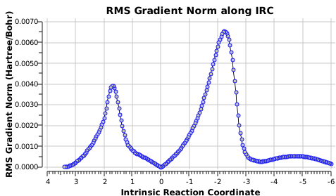
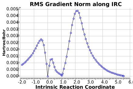
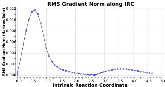
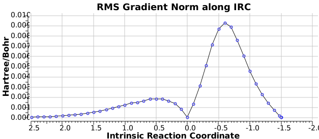
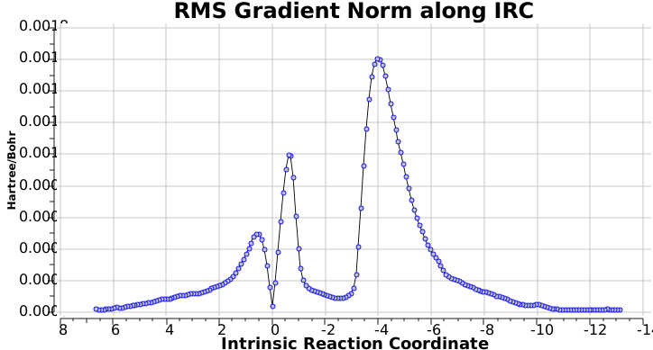
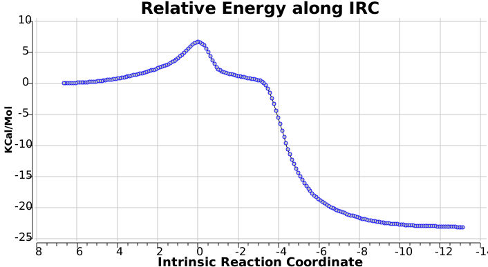
You can see this oddity reflected in the gradient norm of the IRC, which at IRC -1.5 suddenly acquires a new feature, the formation of the second bond. The lesson here is to remember that bonds do not have to form at the same time, they can instead follow, one after the other.

The two different dimers that result from the bifurcation are not in fact identical, they are mirror images (diastereomers because of the methyl group) of each other. They can in turn be inter-converted by a Cope rearrangement, a [3,3] sigmatropic reaction. The transition state for this process is none other than the green point reached earlier. It is indeed a transition state at a crossroads, connecting two quite different reactions, the Diels-Alder cycloaddition and the [3,3] Cope enantiomerisation of the dimer product. Such a reaction has been christened a bispericyclic reaction, one truly at a Y-junction.

Who would have thought that such an un-pretentious molecule could teach us so much. You can see this and many other examples of pericylic reactions in my course on the topic, available on an iPad by clicking here.

Postscript: I have managed to run a full IRC on the system without the methyl perturbation.

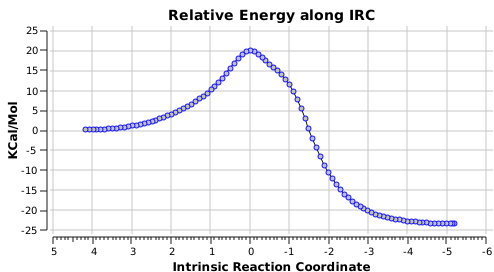
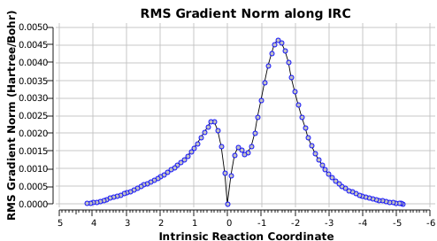
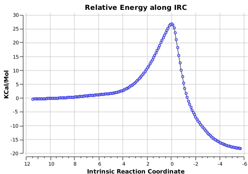
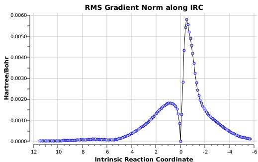
The bifurcation point (green dot) is clearly seen in the following two plots at a value of  IRC +1.0

The first curly arrows. The dénouement.

Monday, July 23rd, 2012

Recollect, Robinson was trying to explain why the nitroso group appears to be an o/p director of aromatic electrophilic substitution. Using σ/π orthogonality, I suggested that the (first ever) curly arrows as he drew them could not be the complete story, and that a transition state analysis would be needed. Here it is. 

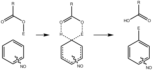
Let me set the scene on how this might be done. Although aromatic electrophilic substitutions are the grand-daddy of all mechanisms, they present some computational challenges. An electrophile is needed, and this is normally represented by E+. This reacts with an aromatic ring to form (so the text books show) a charged Wheland intermediate. A second stage then takes over, whereby a base (B:) abstracts the ring proton to give BH+ and the substituted product. This is clearly an ionic mechanism. And if one does not forget the counter-ions in all of this (see my post on not forgetting them!), it is an ion-pair mechanism. But in relatively non-polar media, need ion-pairs form? A little while ago, I speculated that the two stages could be conflated into one, concerted, pathway. That pathway is shown above. I decided that this was a convenient template upon which to test the directing influence of the NO group. My model is going to be E=NO, R=CF3 (OK, largely because I already had that template to hand; I daresay E=Br might also be appropriate using e.g. acetyl hypobromite) and conducted in dichloromethane as simulated solvent. The transition states (ωB97XD/6-311G(d,p)CPCM=DCM) turn out as below.

Transition state for p-electrophilic substitution. Click for 3D.

This is a concerted reaction (no Wheland intermediate) as the IRC shows, although the relatively long O…N=O bond suggests that it is at least partially ionic/ion-pair like (if you are wondering if there are any examples in the literature that implicate a concerted mechanistic replacement for the Wheland intermediate, you might want to take a look at this one.)

The alternative transition state, leading to m-substitution, is calculated to be 0.7 kcal/mol lower in its free energy activation barrier.

Transition state for m-substitution. Click for 3D

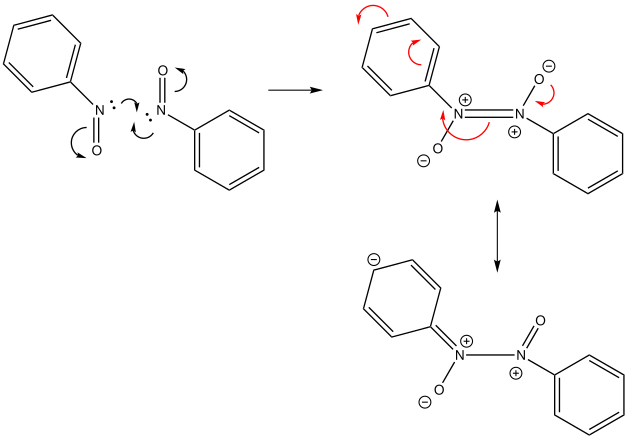
So if the nitrosyl group itself appears to be m-directing (a more complete investigation would test this for other electrophiles), why is the product p-substituted? Well, I also showed that nitrosobenzenes can easily dimerise, as shown below. This species now has a π-mesomeric resonance shown with red arrows below which really does promote the attachment of an electrophile in the p-position. This is now perfectly allowed; no issues of σ/π orthogonality here!

So the dénouement I suggest is that the experiment on which Robinson based his famous curly arrows can in fact be re-interpreted as indicating that it is the dimer of nitrosobenzene that is involved in its electrophilic substitution, and that the monomer (as with nitrobenzene) is actually m-directing. In effect, that dimerisation (which involves two nitrogen σ-lone pairs), bifurcates one of them into a π-pair, and this pair can now safely resonate with the aromatic ring to direct electrophiles.  

The first ever curly arrows. And now for something completely different.

Saturday, July 21st, 2012

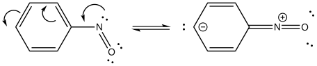
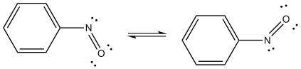
The discussion appended to the post on curly arrows is continued here. Recollect the curly arrow diagram (in modern style) derived from Robinson’s original suggestion:

The pertinent point is that the angle subtended at the nitrogen atom evolves from being bent (~115°) on the left, to linear (180°) on the right. The nitrogen hybridisation changes from trigonal (sp2) to digonal (sp). Because of this, the scheme must represent a reaction rather than a resonance. What kind of species is the molecule on the right? A ωB97XD/6-311G(d,p) solution of the wave equation indicates it is a transition state. The normal mode indicates that the nitrogen atom is moving out of the plane of the ring, evolving the C=N double bond back into having a nitrogen lone pair, and apparently on the way to a most interesting non-planar valence-bond isomer of nitrosobenzene. You might have noticed a nitro group has appeared in the 4-position. I did this to try to stabilize the negative charge in this position shown on the right above to prevent it from being a transition state; this subterfuge failed!

The linear form is a transition state. Click for 3D

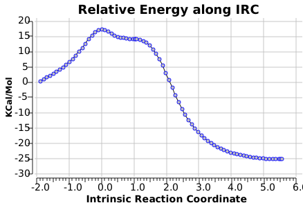
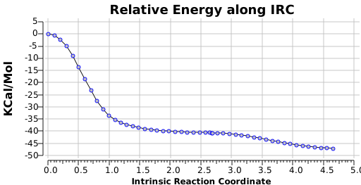
What about an IRC (intrinsic reaction coordinate)? It starts off downhill from the transition state at IRC = 0.0. To quote Monty Python, and now for something completely different. At IRC 2.65, something does indeed happen, a most unusual feature in potential energy surfaces; a bifurcation point.

I am going to have to explain this. Normally, a transition state (a saddle point of order 1) connects two minima. But a bifurcation means that one transition state leads directly downhill (without any intervening minima) to another transition state. When the lower energy transition state is reached, the potential bifurcates, since it now has two (equal) directions for it to continue its downhill descent. Our IRC at this point has to somehow chose which of these two to take. In fact the choice is made randomly. To be precise, small so-called round-off errors in computing the derivatives of the path favour by a tiny tiny margin one of the pathways over the other, and so off it heads. As you can see below, this second pathway involves an (anticlockwise) rotation of the nitroso group (it could also have chosen clockwise).

That rotation can now be represented by the following.

I continue to be surprised at where we have arrived at from Robinson’s original curly arrows; bifurcated potential energy surfaces. Well, that introductory student tutorial to curly arrow pushing is going to have to cover a lot of ground! 

[qrcode content=”Robinson” size=”200″ alt=”QRCode” class=”CLASS_NAME” align=”right”]

The first curly arrows…lead to this?

Friday, July 20th, 2012

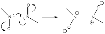
Little did I imagine, when I discovered the original example of using curly arrows to express mechanism, that the molecule described there might be rather too anarchic to use in my introductory tutorials on organic chemistry. Why? It simply breaks the (it has to be said to some extent informal) rules! Consider the dimerisation of nitrosomethane (in fact a well-known equilibrium).

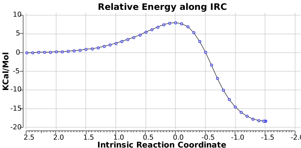
Curly arrow pushing for this reaction results in two arrows heading in effect towards the same bond, at the same time! The result has two adjacent nitrogen atoms each with (formal) positive charges on them, and the N…N bond order goes from zero to two in a single step. Surely this cannot be allowed to happen as shown above? Well, the IRC (intrinsic reaction coordinate) computed from a ωB97XD/6-311G(d,p) calculation is shown below. The barrier is small, the profile uneventful. I conclude that if I ever see a student exam script showing two curly arrows heading directly towards the same bond at the same time, it might even deserve to be graded correct! 


Origins of the Regioselectivity of Cyclopropylcarbinyl Ring Opening Reactions.

Friday, July 20th, 2012

Twenty years are acknowledged to be a long time in Internet/Web terms. In the early days (in 1994), it was a taken that the passage of 1 Web day in the Internet time-warp was ~≡ 7 for the rest of the world (the same factor as applied to the lives of canines). This temporal warping can also be said to apply to computational chemistry. I previously revisited some computational work done in 1992, and here I rediscover another investigation from that year[1] and that era. The aim in this post is to compare not only how the presentation of the results has changed, but how the computational models have as well.

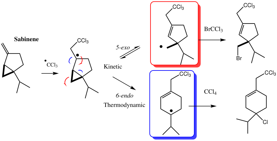
Experiment had shown that Sabinene undergoes a radical ring-opening of the cyclopropane when treated with CCl3 radicals. If BrCCl3 is used as solvent, the kinetic 5-exo product is immediately trapped. If instead the reaction is conducted in the less reactive trap CCl4, the thermodynamic 6-endo product is isolated. The objective was to investigate the origins of these effects. In 1992, computational modelling was limited by the speed and memory of the computers to the following:

  1. Semi-empirical methods such as PM3 (ab initio methods were used only sparingly).
  2. Larger groups (in this case, the CCl3 and isopropyl groups) were trimmed off
  3. Simulations were often for the gas phase only (although the self-consistent-reaction-field was starting to be used to simulate solution).
  4. The properties of transition states were analysed via their molecular orbitals alone, and these were often disconcertingly complex:

The conclusion in 1992 using these techniques found that the transition state for 5-exo ring formation was 3.1 kcal/mol higher than for 6-endo, contrary to the experimental result. With no support from mere activation energies, perhaps slightly desperate recourse was made to an orbital correlation diagram, and the discussion included, inter alia, an arcane feature involving an avoided orbital crossing unique to the 5-exo transition state. Perhaps, in retrospect, rather too arcane for the intended audience, since this is unfortunately not a well cited article.

How might one do things differently (better?) twenty years on?

  1. Here, I start with presenting a (3D) model of each transition state. This was not done in 1992 for reasons of space (the journal format limited the page length very strictly) and of course the journal was only available in printed form (no e-journals then!).
  2. The model itself can be greatly improved (ωB97XD/6-311G(d,p)/CPCM=CCl4).  We now have a DFT calculation, including proper dispersion terms (which PM3 lacks by the way) and good triple-ζ basis set (PM3 is single-ζ), with inclusion of solvation (even though this is a radical, the dipole moments are nevertheless in the range 3-4D, and hence a gas phase model may not be entirely appropriate) and with no trimming off of groups. Crucially (in retrospect), my decision to delete the CCl3 group in 1992 was not a sound one! We have no archive from those days however, so cannot double-check this point. The modern calculation is indeed archived here (although of course whether this archive will itself still be available in 20 years time remains to be established!). 
  3. With modern computers, these new models took about 2.25 hours each to compute (the entire project was done in one working day). The 5-exo transition state is shown below:
  4. The presentation of this model can also be improved from that available 20 years ago. As usual, just click on the image above to see it.
  5. The free energy of activation, ΔG298 = 10.6 kcal/mol, is an entirely reasonable value for radical ring opening of a cyclopropyl (this value is mysteriously not reported in the 1992 version, for which I also take complete blame).
  6. The isomeric 6-endo transition state (which is observed to be kinetically slower) indeed now has the higher calculated barrier (ΔG298 = 11.5 kcal/mol) and this value corresponds to a process about 5 times slower than 5-exo. Recollect, PM3 obtained the opposite result, but possibly that was because the CCl3 group was not present in the model.
  7. We can learn a little about the dynamics of the reaction path; note how the isopropyl group rotates near the end of the ring-opening, due to some form of σ-conjugation no doubt.
  8. Instead of delocalised molecular orbitals, we are going to present localized NBOs, and in particular look at the localised effect to the C-CCl3 bond. The orbitals for the 5-exo transition state are shown first. The red-blue is the C-CCl3 σ* NBO orbital, the purple-orange is the highest energy doubly occupied NBO orbital (these two are selected because they represent a pair with a small energy gap, which means a larger interaction energy). Where blue and purple, or orange and red overlap, we have a stabilizing influence.
  9. The equivalent pair of NBOs for the 6-endo transition state overlaps much less well (click on image to get a rotatable 3D model to see for yourself). 
  10. Nevertheless, the 6-endo transition state manages an overlap between the highest singly occupied NBO and the C-Cl σ*, but because it involves only one, and not a pair of electrons, the stabilizing effect is smaller.
  11. What we conclude is that at the transition state, the 5-exo isomer has the more stabilizing orbital overlaps, but that beyond the transition state, the greater thermodynamic stability of the 6-endo isomer takes over.

Well, here we have a refresh of some chemistry analysed 20 years ago, and done with the help of software and hardware tools that have advanced considerably during this period. One may only speculate what another refresh in 20 years time might bring! 

References

  1. R.A. Batey, P. Grice, J.D. Harling, W.B. Motherwell, and H.S. Rzepa, "Origins of the regioselectivity of cyclopropylcarbinyl ring opening reactions in bicyclo [n.1.0] systems", Journal of the Chemical Society, Chemical Communications, pp. 942, 1992. https://doi.org/10.1039/c39920000942

The first ever curly arrows.

Friday, July 20th, 2012

I was first taught curly arrow pushing in 1968, and have myself taught it to many a generation of student since. But the other day, I learnt something new. Nick Greeves was kind enough to send me this link to the origin of curly arrow pushing in organic chemistry, where the following diagram is shown and Alan Dronsfield sent me two articles he co-wrote on the topic (T. M. Brown, A. T. Dronsfield and P. J. T Morris, Education in Chemistry, 2001, 38, 102-104, 107 and 2003, 40, 129-134); thanks to both of them.

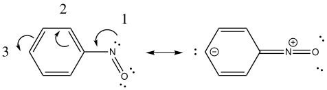
This diagram dates from 1924, and is to be found in an article published by Robert Robinson (J. Soc. Chem. Ind., 1924, 43, 1297, a journal difficult to get hold of nowadays). Here, Robinson was trying to explain why the nitroso group is o/p-directing in aromatic electrophilic substitution. Whilst the notation is remarkably modern, some aspects do need explaining. 

  1. Robinson shows the nitrogen lone pair (arrow 1) as a line, and not as we now do, a double dot.
  2. Similarly, he shows arrow 3 ending at a line. We now do not show this in the starting structure, but reveal it in the final result, as above on the right, and again shown as a double dot.
  3. Similarly, he shows a + charge on the nitrogen at the start, whereas we now show it as the outcome of the process.
  4. If Robinson intends to create a +ve charge, then he really should balance that by showing the creation of a negative charge in the p-position of the ring. He does not balance his charges! 
  5. As was the custom at the time, the benzene ring itself is not represented in the Kekule mode (which of course should have been well known in 1924) but as what looks to us now as cyclohexane. It must have been the case in 1924 (and for several decades after) that cyclohexane itself was not regarded as an interesting system, and hence there must have been little confusion about drawing benzene as (modern) cyclohexane. The implied semantic of showing such a ring was that it represented benzene.
    1. But this way of drawing it leads to really difficult issues. Thus Robinson’s arrow 2 departs from what looks to us like a single bond, in which case no bond would be left. Robinson of course means implicitly that arrow 2 reduces the bond order by one, and if we start with a double bond from a Kekule structure, that the bond is reduced to 1, not zero, as is shown in the modern notation above.
    2. Likewise, the destination of arrow 2 in Robinson’s notation clearly creates a double bond. Which again is an issue, since he is not showing the double bonds. The trouble really arises because Robinson does not illustrate the outcome of his process.
    3. Finally, whereas arrow 1 starts at a line representing a lone pair, that line is disconnected from the N. However, the destination of arrow 3 appears to create a bond, not a lone pair.

Now that we have clarified Robinson’s meaning, what else can we say about Robinson’s structure.

  1. It is important to realise that in 1924, the 3D characteristics of electrons (their wavefunction) were not known. Looking at the modern version of the diagram, chemists realise that when a double line is drawn, the two are not the same. One line represents a σ-bond, the other a π-bond. We recognise that the two have different spatial characteristics. Hückel it was who showed that in planar aromatics, the two sets are in fact orthogonal, and do not mix. At which point we need to sort out what the three arrows in Robinson’s diagram represent. Arrows 2 and 3 we recognise as π-arrows. But what of arrow 1? I decided to do a search of the Cambridge data base for nitrosobenzenes, finding 22 sets of coordinates. In all except one, the two atoms of the nitroso group were co-planar with the six of the benzene ring. We now know of course that this places the nitrogen lone pair firmly in the plane of the eight atoms, and hence of a σ-type. Strictly therefore, it is orthogonal to the π-arrows and cannot be mixed with them. The solution of course is to first rotate the nitroso group by 90° to bring the nitrogen lone pair into conjugation with the π-system, whereupon Robinson’s arrows now “work”. 
  2. On a more minor point, we recognise that the nitrogen lone pair occupies a trigonal position, and so we draw the C-NO group as bent, rather than linear as Robinson did.
  3. If the co-planarity of the nitroso and benzene rings is retained, then the only way to draw the arrows is in the opposite direction to Robinson, resulting in the creation of a -ve charge on the oxygen and a +ve charge on the p-carbon. This of course is the resonance we now show for the nitro group, and implies m-direction, not o/p
  4. Which raises the fascinating question. Why, if the structure of nitrosobenzenes appears to be planar and not rotated, is the nitroso group nevertheless observed to be an o/p director? The answer of course must be in looking at the properties of the transition state, and not the starting material itself. But in 1924, the concept of a transition state itself was not yet recognised.

So this little blast-from-the-past example still gives us lots to think about!

Dynamic effects in nucleophilic substitution at trigonal carbon (with Na+).

Thursday, July 19th, 2012

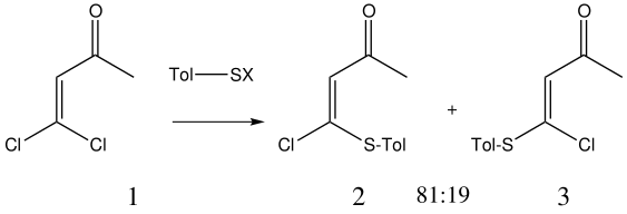
In the preceding post, I described a fascinating experiment and calculation by Bogle and Singleton, in which the trajectory distribution of molecules emerging from a single transition state was used to rationalise the formation of two isomeric products 2 and 3.  In the present post, I explore possible consequences of including a sodium cation (X=Na+ below) in the computational model.

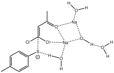
Sitting down to construct such a model, one is immediately faced with important decisions. Na+ comes with baggage, namely groupies in the form of solvent molecules and ionic bonding. The latter means less certainty regarding where to place the ion (covalent bonds have that nice attribute that their orientation and length is pretty predictable most of the time). I decided to construct the model shown below, using not one Na+ but two (such structures are known from the Cambridge crystal data base), the second Na+ being charge balanced by hydroxide anion.

The resulting transition state (B3LYP/6-31+G(d,p)/CPCM=ethanol) is shown below, and the free energy activation barrier, ΔG is 11.7 kcal/mol, well down on the value obtained using X=H+, and entirely reasonable for a reaction occurring at room temperature. This suggests that the model is not unreasonable (but of course does not prove it is the best).

The geometry of this transition state is significant. Of the two C-Cl bond lengths, the shorter (click the image above to inspect the model) is the one cis to the carbonyl (subsequent elimination of which would result in formation of the major product 2). But an IRC reveals what happens next. Recollect that when X=H+ a tetrahedral intermediate is formed that then collapses with elimination of H3O+Cl. This time, no intermediate is seen on the IRC, and the requisite C-Cl bond is broken to form 2 in a concerted (but very asynchronous) manner, and in the manner reported by Bogle and Singleton for a model without counterion and explicit solvent.

Notice how preparation for eviction of the C-Cl bond only starts after the transition state is passed. The forces on the departing chloride start to grow after the dihedral angle of the Ar-S-C-Cl system has become antiperiplanar (IRC -3), resulting in the anion shooting out towards one of the two Na+ cations to form solvated NaCl.

So we now have a rather more complete model. But is it yet complete enough? How would one go about evicting the other chloride, resulting in formation of 3? I think it is fairly clear that the model will have to be enlarged yet again, this time to include at least one more Na+ located on the other side of the carbonyl, and ready to receive the anion. Possibly at least another two water molecules and one hydroxide anion would be required to surround this cation. Clearly, such a model would have grown substantially compared to the original one (Occam might not be happy), and that we are gradually edging towards having two quite separate transition state models to account for each of 2 and 3. At this stage, it would be interesting to apply Bogle and Singleton‘s direct dynamics model to try to establish if each transition state leads to only one product, or whether either of these transition states could result in cross-over to the other product.

I have no feel for whether the  transition state presented here can be treated using direct dynamics; if it could, that would indeed be an interesting simulation.

Dynamic effects in nucleophilic substitution at trigonal carbon.

Monday, July 16th, 2012

Singleton and co-workers have produced some wonderful work showing how dynamic effects and not just transition states can control the outcome of reactions. Steve Bachrach’s blog contains many examples, including this recent one.

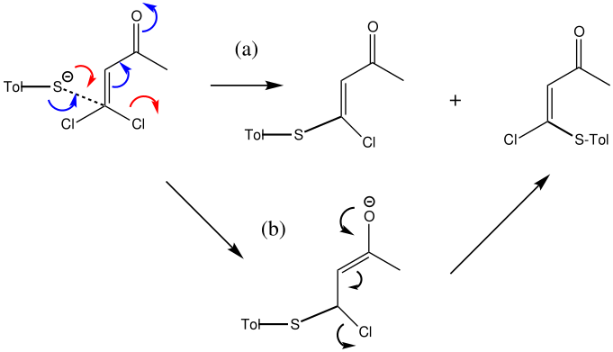
This shows that tolyl thiolate (X=Na) reacts with the dichlorobutenone to give two substitution products in a 81:19 ratio. Singleton and Bogle argue[1] that this arises from a single transition state, and that the two products arise from a statistical distribution of dynamic trajectories bifurcating out of a transition state favouring 2 over 3. Steve puts it very elegantly “I think most organic chemists hold dear to their hearts the notion that selectivity is due to crossing over different transition states“. When I read this, Occam’s razor came to mind: could a simpler (in this casemore conventional) answer in fact be better? 

My thoughts in fact followed a point I have been making here recently, the principle that modelling a complete system is probably better than a partial one. Now, if you look at Figure 1 of the Singleton/Bogle article, captioned “Qualitative energy surface for the reaction of 1 with sodium p-tolyl thiolate” I was struck by something missing; the sodium (X=Na), and possibly also explicit solvent (ethanol). I wanted to see if these missing components may influence the mechanism.

The red arrows follow the proposed mechanism (a), whereas the blue arrows represent a more conventional 1,4-nucleophilic addition to form an intermediate enol anion, this then eliminating to the final product. Singleton & co. explored the potential energy surface using the following computational model: B3LYP/6-31+G(d,p)/PCM(ethanol) for the anionic system (defined by setting an overall charge of -1 during the calculation), finding the potential energy surface corresponded to path (a). They then went on to explore the dynamics of the system emerging out of this single TS, showing that in fact both products would be formed in more or less exactly the ratio observed. 

I thought two things could be considered missing from this model; X+ (the counterion) and explicit solvent (continuum solvent was invoked using the PCM model). On the latter point, I have thought for a little while that there are two types of solvent; those which act via their dielectric field, and those that act via hydrogen bonds. Ethanol does both, and so in this case (I argue) it should be explicitly included (actually, in the first instance it can be approximated using water instead of ethanol). The missing counter-ion is a greater challenge. In what follows I am going to approximate it too, using H+ (Na+ itself I reserve for a future post). The objective is to find out what (if anything) changes when this more complete model is built. It is shown below as the first transition state encountered. Its features include:

First transition state TS1. Click for 3D

  1. Two explicit solvent (water) molecules.
  2. A H+ (I will discuss Na+ in another post), attached to one of the water molecules as a hydronium ion.
  3. The hydronium ion bridges to the carbonyl group (this is the final optimised position; the second water molecule serves only to H-bond to the hydronium ion). 
  4. This overall system is neutral, charge=0 (I like to say it might be found in a bottle or flask; pure anions of course cannot be bottled). 
  5. The model used was B3LYP/6-31+G(d,p)/CPCM(ethanol); I find the CPCM method to be better for calculating intrinsic reaction coordinates (IRC).
  6. Using this transition state to initiate an IRC shows that the presence of this solvent bridge allows X (=H+) to smoothly transfer from sulfur to oxygen as part of a concerted process. This avoids excessive build up of charge separation.
  7. This now forms an intermediate (we are clearly following path (b) and not path (a) now). This is because the enolate anion is stabilised by protonation and a hydrogen bond from the proton to the solvent water, and so this becomes an explicit intermediate in the potential energy surface.

    Intermediate in reaction. Click for 3D

This intermediate now collapses along path (b) to the final product, via the transition state shown below. Again, an IRC shows a solvent bridge allows X to be concertedly transferred, this time from the oxygen to form hydronium chloride and 2 (I have not yet found the equivalent pathway to 3, but given the hydrogen bonds involved it is bound to be different).

Second transition state TS2. Click for 3D 

ΔG (kcal/mol) along this sequence is 1 (0.0), TS1 (28.2), Int (8.0), TS2 (12.6); the intermediate existing only in a shallow well of 4.6 kcal/mol. The activation barrier is on the high side (the reaction occurs easily at room temperature), and it might be expected that (in part) this might be due to using X=H+ rather than X=Na+ for the model. Watch this space!

What might we conclude from this? That the presence of additional molecules (H3O+ and H2O) can result in structures which can depend on other features of the molecule, in this case the carbonyl group, one that plays little role in mechanism (a). In path (b), the carbonyl group is far from passive, receiving and then releasing X during the course of the reaction. This must mean that the transition state for forming product 2 may indeed be a separate one from the transition state for forming product 3, since the relationship of these two to the carbonyl is different. To re-quote Steve again “I think most organic chemists hold dear to their hearts the notion that selectivity is due to crossing over different transition states”.

Perhaps the explanation might indeed be due to different transition states rather than different dynamics? Clearly, more research needs to be done; I for one do not regard the case as closed on this example just yet.

References

  1. X.S. Bogle, and D.A. Singleton, "Dynamic Origin of the Stereoselectivity of a Nucleophilic Substitution Reaction", Organic Letters, vol. 14, pp. 2528-2531, 2012. https://doi.org/10.1021/ol300817a

More joining up of pieces. Stereocontrol in the ring opening of cyclopropenes.

Thursday, July 12th, 2012

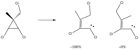
Years ago, I was travelling from Cambridge to London on a train. I found myself sitting next to a chemist, and (as chemists do), he scribbled the following on a piece of paper. When I got to work the next day Vera (my student) was unleashed on the problem, and our thoughts were published[1]. That was then.

This is now. I have just finished a post on ring-opening reactions of oxirene, a 4n electron anti-aromatic ring. I was casting around for an example of a calculation done just before the modern Internet era, and happened upon the above. Although this was a mere 20 years ago, much of the detail had faded; I had not thought much about it in the intervening years, but I did recollect that although we had attributed the high stereoselectivity shown above to a stereoelectronic orbital alignment, I was not entirely happy with the interpretation. Put simply, we had relied on a molecular orbital diagram, and this diagram (in resplendent colour in the journal, one of the few being so published at that time, and for no colour charge to boot) was just too complicated. Arguably it was the fixated complexity (I remember at the time that it looked complicated no matter what the viewing angle was) that set me on the road to the use of the Web, and ultimately here to this blog. So I thought a re-analysis using modern algorithms and presentation might help simplify. The newly recalculated transition state (ωB97XD/6-311G(d,p) looks like:

Transition state for ring opening of a cyclopropene. Click for 3D.

  1. The reaction is a 4n (n=1) electron electrocyclic ring opening, and so according to the rules, should proceed with the formation/cleavage of an antarafacial bond. You might think that there are not quite enough substituents to reveal this stereochemistry, but there are if the carbene lone pair is included. So how to add the lone pair?
  2. Well, its coordinates can be computed using the ELF (electron localisation function). The relevant lone pair is ringed in red below. Using (old technology, i.e. a static figure) you may choose to believe me when I argue that this lone pair is above the plane of the forming ring from the perspective shown, whilst the terminus of the bond it forms is to the bottom. This defines an antarafacial component. Well, I might have carefully manipulated the viewing angle to show this. Now, in 2012 rather than 1992, you can load the 3D coordinates by clicking below, and check for yourself!

    Lone pair centroid for the transition state. Click for 3D

  3. What about the stereo-control? Take a look at the angle between the axis of the C-Cl bond (atoms ringed in blue) and the centroid of the carbene lone pair (red). It is about 162°, or almost anti-periplanar. A magic orientation in organic chemistry. Time to attack the orbitals again. Our published diagram looked as below. It shows the HOMO aligning with the LUMO+2 (if your eyes are not distracted by all the other detail).
    But we can now simplify such a complex molecular orbital by using instead a localized version, an NBO. A little explanation is needed. The NBO orbital shown with red/blue phases is antibonding for the C-Cl bond. That with orange/purple is the carbene lone pair. Where orange overlaps with red, we have a positive overlap that stabilises the system. The NBO E2 perturbation energy is around 4.6 kcal/mol. Although this may seem small, it is actually quite large for a through-space interaction of this type. It is this stabilisation (amounting to ~ 1.6 kcal/mol in free energy) that accounts for the high selectivity for the stereoisomer shown above.

    NBO for transition state. Click for 3D.

Well, I think that the passage of 20 years has enabled us to tidy up the origins of the stereoelectronic effect responsible for controlling this reaction, and to produce clearer diagrams which the reader can interactively explore for themselves. It did take 20 years to join things up though!

References

  1. M.S. Baird, J.R. Al Dulayymi, H.S. Rzepa, and V. Thoss, "An unusual example of stereoelectronic control in the ring opening of 3,3-disubstituted 1,2-dichlorocyclopropenes", Journal of the Chemical Society, Chemical Communications, pp. 1323, 1992. https://doi.org/10.1039/c39920001323